


Parametric Design combined with GIS, scanned data and BIM
- Michele Calvano
- 5 mar 2018
- Tempo di lettura: 5 min


This post is to show our presentation in Oslo about a research that thanks to McNeel and Graphisoft tools, has investigate the possibility to reconstruct the cities by using GIS and BIM models.
"Just a short description of us:I am Michele Calvano, architect and researcher, expert in parametric procedures for drawing and co-founder of the Arfacade, a group specialized in façade engineering;Next to me there is Mario Sacco, architect and BIM expert; important component of Archiradar, the most important BIM web site in Italy where you can find solution for building Information modeling.

I want to start with an overview of the case study. As you know Since August 2016, the center of Italy has been hit by a series of seismic events that have completely destroyed some cities along the Tronto Valley as Amatrice and Accumoli. (Don’t exist anymore)

After the disaster we noticed that we have no information about our historic centres and, above all, we don’t have information about Italian small cities in general, that is a problem not only after a disaster, but also during the ordinary administration of our country. So our solution has been to create a 3D database capable to contain different information about landscape, cities and buildings.

We decided which kind of data are useful for our goal, but above all, understood which data are easily available. In the slide I show three kind of data useful to construct and inform a 3D model: the most accessible data comes from the web, where we can find geometries and metadata (for example GIS data); less available are data from a direct survey, because you have to go there and often there is no possibility to take measure with a metric tape or a total station. But where is possible, we can create points cloud by using a camera or a Laser Scanner. At least, on place we have to understand styles of doors, windows walls etc…. By observing.

With all these data we developed a workflow using tools by McNeel and Graphisoft. Look at this slide. After acquiring data, in the 2nd phase of sythesis we created a definition with which normalize data and push them in a data flow capable to transform 2D geometry inside the GIS file in a 3D shape. The resulting shape is a sort of hull, where is impossible to distinguish architectural objects. With Grasshopper we deconstruct the shape in faces respecting what they representing. Thanks to the Live Connection by Graphisoft we get translate faces in architectural object inside ArchiCAD. So the final model is a BIM model.

Going in the deep, In Italy, some country’s Administration put landscape information on the web. Lazio Region upload GIS files adopting the shape format as a way to describe Its territory, so information are freely gettable by a simple download from wherever you are.

Let’s see the contents of a shape file. It is composed by layers, everyone with different information. For our work we used three layers describing territory in a 2D representation and with attributes.
One layer is composed by curves. If I select….. Another layer is composed by closed polygon that are the shape of the building…. Inside every polygon there are two points with two different code. One represents the base elevation from the line of the see, the other represents the elevation from the top of the building.

In the slide there is a point cloud representing the situation after the earthquake, so it is partially useful for a 3D reconstruction but it increase Its value if It is matched with other data.

Observation on place are very important to understand styles of architectural object: for example the number of stores, the thickness of the walls and slabs, the materials and finishes of doors and windows. We translated attributes in numbers and put them in a spreadsheet.

Grasshopper is a Visual Programming Language generally used to manage simple data that comes from Rhinoceros or from outside sources like Text or Numbers. To manage GIS data you need an add-on called @It, you can find a lot of important tools in the web site www.Food4Rhino.com. New components allow Grasshopper to introduce information from shape file inside the procedure.

Here It is the 1st part of procedure we adopted. With @It, in Grasshopper we deconstruct GIS data in geometric entities and attributes. We design a GH definition that use attributes to transform the entities. For example, if I know the basement shape of a building and I know Its elevation I can transform the 2D boundary by an extrution; thanks to Grasshopper I can solve hundreds of these problem in one time. I can do the same with the terrain working on the contour lines. Live Connection allows to introduce 3D buildings and Terrain as a Morph in Archicad. In archiCAD we can add new attributes to Morph and fill the new strings with data from the spreadsheet.

About the terrain, the first step is introduce the shape file in Grasshopper and split geometries from elevation attributes, and than combine again by using the transformation Move; instead move one by one, with a parametric procedure, we can move all in one time but in the proper elevation. The aim is create a polyhedral surface, so we extract points from curves and connect together by an un-structured mesh. It is impossible to put this kind of mesh in Archicad by using the mesh tool.

So the second step is create a structured grid of points on the horizontal plane and project them along the vertical line until they hit the mesh in the space. The dimension of the matrix is according to the part of landscape we wont to represent. The image on the left, show in green a matrix of regular points useful to create a structured mesh suitable for the mesh tool of ArchiCAD, on the right.

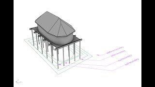
Create the buildings means open the layer of the shape file that contains information about the profiles of the building. Inside every profile there are two points, one with an attribute to describe the elevation of the base of the building and another one to describe the eaves elevation. In Grasshopper we can combine the geometries with the two attributes, creating two parallel polygons. Between two curves we can create a solid. At the end in Rhino we get see the whole model with a low resolution.

A special components from Live connection allow us to construct the model you can see on the right. With the Morph component I can Import in Archicad buildings coming from the live definition done in Grasshopper. Imputs for this component are the mesh previously created; typical settings to describe the object in ArchiCAD (name of the layer for example) and a sort of switch to activate the connection between component and ArchiCAD. The same is done with Mesh tool. I said Live Definition because changing the input data the model both in Rhino and ArchiCAD will immediately change.

In the following part of the work, we add more data inside the procedure. So, to increase the accuracy of the model we upload the point cloud. Inside ArchiCAD is easy to draw simple geometries representing opens like windows and doors. These geometries are object informed by attributes previously collected in spreadsheets.

Now It is time to deconstruct, Live connection is able to collect Morph and Object inside grasshopper and deconstruct them. The output are geometries and all the settings collected until now. Last step is combine data and geometries in special components which translate Morph in walls, slabs and roofs; and Object in doors and windows.

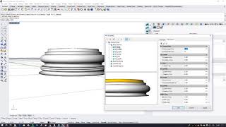
Here we show how we deconstruct a solid to translate faces in architectural object: it is important to calculate the angle between normals and zed axes, If the angle is 90 degree face will be a wall, if different will be roof or slab.
Below the video done by us for Graphisoft that show the whole work


Comments